After a previous report on interoperability and agricultural standards, I’m back with a new popularization work focused here on communication protocols in agriculture. This is an important subject where it is clear that few people really understand anything about it…
If I talk to you about MQTT messaging protocol, communication via NB-IOT, Sigfox or LoRaWAN, or even the OSI conceptual model to present the way networks communicate with each other, you are totally at ease? Or maybe you have already taken your legs to your neck… Are you still there?
Between anglicisms and acronyms, confusions are common. Nevertheless, sometimes it is enough to simply unroll the acronyms to realize that you didn’t really understand much or, on the contrary, to finally open your eyes to concepts that you had trouble understanding.
If, for many, this subject is transparent (and sometimes without interest) insofar as it would be the providers of tools and services to take care of it, it is however a pity because understanding the communication protocols allows to better apprehend and understand the Internet of Things.
For farmers, it is an opportunity to open their curiosity, to develop their general culture, and perhaps and above all to understand what connected objects are able to do and not to do. The whole to avoid taking powder to the eyes …
This report on connected objects, and more specifically on communication protocols in agriculture, is also an opportunity to promote all the knowledge that is beginning to be capitalized on the directory of digital tools for agriculture (https://www.lesoutilsnumeriquesdesagriculteurs.com/). In addition to serving as a collaborative watch, this platform is now used to take a step back on the digital tools in place and to identify trends.
This article was written in close collaboration with Nicolas Daüy (Furgo company) and Simon Moinard (AgroTIC Services – with the Mobilab device). I would like to thank them for the time they have given me. Several articles, reports and seminars have allowed me to complete the feedback from the interviews.
Enjoy reading!
Important preamble
Even if we are going to travel together in the world of connected objects in agriculture and discuss a lot of technical subjects, we will remain in rather theoretical considerations and we will not go into operational matters. Basically, I apologize in advance but I will not explain how to deploy your network of connected objects on your farm, how to install your WiFi box or how to make your LoRa chip compatible with the LoRaWan communication protocol! I have never installed myself my own LoRa station, that’s to say…. My technical experience on the subject is limited to a few distant courses on wireless sensor networks or some very basic tinkering on Arduino boards to try to display a temperature information from a very basic temperature sensor (I don’t even remember if I succeeded).
The pure technique, even if it is becoming more and more accessible, is still quite complicated. So of course, some geeks are doing particularly well (and we are happy for them), but from where I stand, I still sometimes have the impression that Do It Yourself is never far away. When it’s time to industrialize everything, it’s not the same thing anymore.
So once again, it is with humility that I offer you this file. As usual, it is perhaps precisely this naive approach that is interesting, and that allows me to try to put words on concepts that I did not really understand.
In this file, I will try to bring a very particular attention to the vocabulary which, for me, is at the origin of many confusions and misunderstandings. I will also take the opportunity to come back to some abuses of language that, on the surface, may seem insignificant until they start to take a little too much place in our heads.
Please keep this in mind as you read this work !
A first introduction with examples of data paths
How on earth can we visualize on our smartphone (or any other interface for that matter) the data collected (plant data, weather data, soil data…) from a sensor placed in an agricultural plot? The data has actually gone through a whole path, invisible to our eyes, sometimes very short or on the contrary very long, with potentially few intermediaries or on the contrary a plethora. A real obstacle course, you might say… Tracing this path already allows us to understand the technical and technological implications that lie behind the use of these connected sensors. Visualizing this journey is also an opportunity to realize that all the imaginary ideas regularly asserted around the dematerialization or virtualization of the digital world are in fact a farce. Connected sensors impose the existence of a whole IT infrastructure (antennas, cables, servers, micro-controllers…) made of real material.
Let’s take a few examples to get to the heart of the matter.
Don’t worry if you don’t understand all the vocabulary in this section, we will have plenty of opportunity to come back to it in this blog dossier. The idea here is to have a panoramic view and a first awareness of the data journey to be able to dig deeper in the rest of this blog post. Please note that these examples are examples! They are not general truths and there are many ways to achieve the same result (to send the data) – it all depends on the context and the user need. We’ll talk about this later…
FIRST EXAMPLE (Figure 1): Real-time visualization of temperature data from a connected weather station (I’ll take this opportunity to refer you to a previous blog post to go deeper into these stations: https://www.aspexit.com/les-stations-meteo-connectees-en-arboriculture/!). As a farmer, you would like to have a weather data well localized in your plot. You may have a fragmented plot of land or plots of land on significantly different valleys or slopes. You take the plunge, contact a supplier (if you know what to ask for, it’s always better), buy a station and install it near one of your plots. Every day, you follow the temperature data collected by your station in the field in real time on your smartphone. How is this possible?
- The weather station, composed of several sensors (thermometer, rain gauge, anemometer…), is the communicating object. The temperature sensor present on the station measures a temperature level and transfers this data in bits (0’s and 1’s) to a microcontroller present at the station.
- The data is then aggregated on a time step (let’s say every minute) within the microcontroller to recalculate a whole bunch of parameters a bit finer (gusts calculated on a 3s time interval, mm of rainfall summed up on the sending interval, rainfall intensity calculated on a minute…)
- At regular intervals, the station sends a summary of these data in bits by radio waves (via the cellular network or not) thanks to a transmission module installed at the station) to a receiving structure (an antenna managed by a telecom operator such as Orange or an antenna managed by the station). The station is thus not necessarily constantly connected to the cellular network.
- The receiving antenna decodes the radio waves and sends the decoded data via the internet to the database of the telecom operator or the station manufacturer for example).
- The data is then sent to the database of the station manufacturer who provides the web site to format and visualize these data
- As a farmer, you login to your user account on the station manufacturer’s website (from your computer or from the manufacturer’s dedicated smartphone application). To access your data, a computer query is sent to the manufacturer’s database via an API (or to the operator’s database if the manufacturer does not store the data on its own databases). The data is then sent back to you and presented to you in your browser.
- The manufacturer’s database server, by dynamically tracking the temperature data collected in the database, can also send alerts directly to your user account (and not wait for you to connect to the manufacturer’s server)
- The manufacturer can also trigger an update or a setting of the connected station (or rather of the temperature sensor) by sending a request to the operator’s server (for a code update or a setting of the connected tool). This request will be transmitted via the cellular network and, when the station connects to the cellular network to send its data, it will receive the requested update or setting.
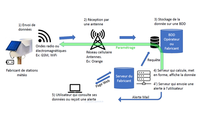
Figure 1: Example of a weather station data path. Credits: Nicolas Daüy
SECOND EXAMPLE : Remote activation of an irrigation pump. You are a geeky farmer and you are irrigating one of your plots with a hose reel. Your pumping station is quite far from your farm. Each trip to the station is quite time consuming and tedious. Whenever you have a problem or need to check your hose reel, you have to go back and forth to the station. After wondering about the technology to be used, how you were going to make your system communicate or what your installation was going to cost you, you decide to install a relatively simple connected object to make your job easier. You set up an actuator controlled by an Arduino microcontroller to automatically activate the buttons on your pump without having to go to your pumping station:
- You send an SMS from your cell phone or smartphone to a microcontroller connected to an Arduino electronic board installed at the pumping station.
- The microcontroller receives the SMS, which is actually a password, and commands the pump to turn on
- The microcontroller sends the command in GSM (via the telephone network) to a stepper motor (servomotor) which activates the button of the pump of the station.
This example makes us see that there are several types of connected objects, for example a sensor (here the smartphone) and an actuator (the actuator). The example may not be the most appropriate one but it allows to raise at least this topic.
THIRD EXAMPLE: Local display of data from a temperature sensor using its own Lora antenna. You are a farmer, a bit geeky and you want to develop an entirely open-source infrastructure free from any external provider.
- The temperature sensor is connected to an Arduino board (programmable microcontroller for beginners).
- A Lora module, installed on the Arduino electronic board, allows to transfer the data from the Arduino board to the Lora antenna that you have installed at home and integrated to The Things Network
- A Raspberry Pi microcomputer with a Wifi module retrieves data from The Things Network servers via Wifi
- The Raspberry Pi sends the retrieved data to a database stored on your local server
- The data is displayed on a small local interface with the Node-Red development tool
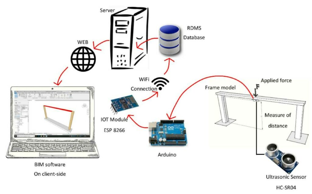
Figure 2. A schematic example of the data path between an ultrasonic sensor used for a distance measurement and a local display on a user’s computer. The ESP8266 module added to the Arduino electronic board allows the object to be connected to the Wifi network in order to send (in the example of the diagram) the data to a relational database (“RDMS” for “Relational Database Management System”)
We continue to take a step back with the last diagram below which, finally, summarizes a certain number of things. We see in particular:
- A sensor that sends data via the Zigbee communication protocol. To be more precise, we should talk about a connected object because this sensor is most certainly connected to a microcontroller installed on an electronic board (Arduino for example). The sensor itself is only used to measure and it is the whole architecture that makes it a connected sensor
- A gateway that makes the link between the connected sensors and different types of servers to communicate via the Internet. In this diagram, the data transmission is done via a local area network (LAN) but it could have been different. This gateway consists of a Raspberry Pi microcomputer and one or more modules to send data to the servers. This gateway makes it possible to manage communication between several infrastructures that do not necessarily communicate with the same protocols. A gateway performs several tasks such as translating communication protocols, processing, encrypting and managing data.
- The database servers (there are several on the diagram) then communicate their data following requests to different utilities (a smartphone application or a web browser) via different communication protocols, respectively a wireless communication (e.g. Wifi or 4G) when we try to call data on a database from our smartphone, or via the ethernet communication protocol for example when we try to call the data stored on a web server from another computer connected to the same network
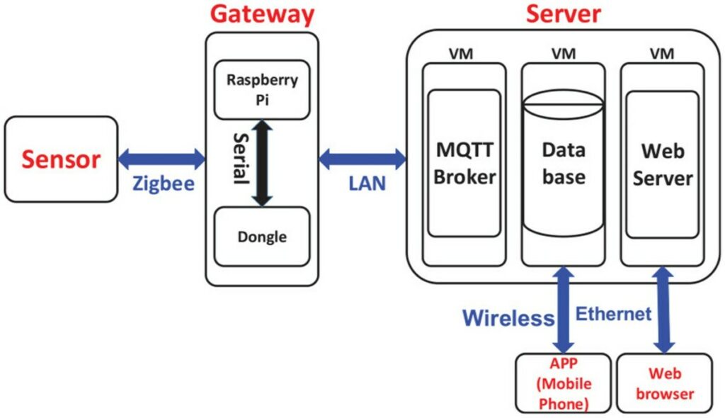
Figure 3. From sensor to smartphone application or web browser: data paths.
A little treatise on connected objects
One may find the parallel quite amusing. Some authors have tried to network what scientists were interested in when they were working on wireless sensor networks (WSN) in agriculture (Abdollahi et al., 2021). After a bibliographic search in a number of dedicated journals (such as “Sensors”, “Computers and Electronics in Agriculture”, or “Wireless Personal Communications”), the authors offer us a nice mesh of all the keywords connected to the work around wireless sensor networks in agriculture (Figure 4). Here we find:
- agricultural applications (actually quite a lot around the monitoring of environmental conditions and water management “smart irrigation”, “aquaculture”, “Precision Irrigation”, “Soil Moisture”),
- concepts closely related to communication protocols of all kinds (LPWAN, LoRa, WSAN, Zigbee, RFID…) or
- themes related to the management of connected objects (Application, Authentication, Fault Tolerance…)
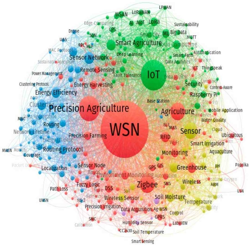
Figure 4. Wireless Sensor Networks (WSNs) in the scientific literature in agronomy. Source : Abdollahi et al. (2021). Wireless Sensor Networks in Agriculture : Insights from Bibliometric Analysis, Sustainable
Is a sensor necessarily a connected object?
SPOILER ALERT: A sensor by itself is not a connected object! If we go back to our examples mentioned at the beginning of this file, the weather station only becomes connected because there is an infrastructure that allows to send the data, a server to store the data and web pages (or others) to display these data. The Internet of Things (IoT) is the infrastructure that allows to extend the internet network to objects in the physical world, i.e. to the sensors we install in agricultural plots or in the environment, so that we can send the data from these sensors on the internet network and display them like any other data on the web. It’s the bridge between the physical world and the virtual world – although we’ve already discussed that there’s not much virtual behind it.
So let’s go back a bit now to what makes up a connected object (Figure 5). With the examples from the beginning, you should now have a few marbles in your head. A connected object is at least :
- A “data acquisition” part: i.e. one or more sensors and at least one converter to transform the analog signal of the sensor into a digital signal (made up of 0 and 1). We speak of CAN for Digital Analog Converter. It is this digital signal that can be read and used by all the network infrastructures. In an agricultural context, we can imagine adding a small GNSS antenna (which acts as a geolocation data sensor) to monitor the positioning of the connected object in real time.
- A “data processing” part: here we find a calculator and aggregator (the microcontroller) to which the sensor is connected, a device to quickly store the data and ensure the memory of the connected object, and an operating system (for example installed on a Raspberry Pi microcomputer)
- A “data transmission” part materialized by modules installed on the microcontroller to transmit or receive data via wireless communication protocols. Today, we almost never design objects that have a microcontroller without adding a wireless connection (WiFi, Bluetooth, or other). The telecommunications chip can be sold directly with the microcontroller.
- A “power source” part to power all the units of the connected object (a battery for example). Some connected objects are associated with energy generator systems to be more autonomous (we think for example of small solar panels that would power a connected object installed in the field).
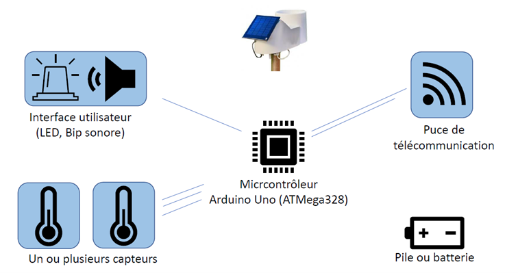
Figure 5. Simplified diagram of a connected object (here a connected weather station)
All these devices are connected to the same electronic board (the example of Arduino was given). It’s really like when you played with Legos when you were younger but this is with electronics – it’s the Lego of electronics. The Arduino board is really made for the interoperability of electronics. This board is compatible with many different communication protocols, has analog and digital outputs, uses a development language also called Arduino, and can read a value every microsecond. The Arduino board has just enough memory to hold the code previously designed in C/C++ language on the computer. It is however possible to add a storage space (like an SD card to collect a large amount of data).
The microcontroller is really the central device of the connected object that makes all the elements connected to the electronic board interact. Within this ecosystem (inside this electronic board), data can transit in several ways.
The microcontroller will for example communicate :
- with a LoRa telecommunication chip in SPI wired protocol. This LoRa chip will transform the received signal and send it to the LoRa antenna afterwards.
- with a radio chip in serial wire protocol (RX/TX for Receive/Transmit). The microcontroller will make the link with the SIM card reader and the potential radio components present on the electronic board and will send these data to the radio antenna also installed on the electronic board. This antenna will make the link with the relay antenna of a third party operator or a locally installed antenna.
The sensors will for example send their data after having converted them into voltage and amplified :
- in an analog form (it is then the microcontroller that will read and convert this signal into a digital signal),
- in a digital form directly:
- in a ” Serial ” format with an RX/TX protocol – the sensors then have pins for transmitting and pins for receiving the signal (voltage)
- in ” SPI ” format: the data are not coded. There is simply a pin with an identifier for a sensor, which makes it easier to find
- in ” I2C ” format (the sensor must be I2C compatible): it is a cable which allows the data to transit at a fixed time (a clock is present). At the beginning of the signal, the first data bits always identify the sensor that sends the data – the microcontroller knows what it is talking about.
- We can also mention the OneWire format, i.e. communication via a single wire
Note that the SPI and I2C formats that I have slightly mentioned are not specific to the Internet of Things. The USB protocol – widely democratized – is also used to transfer data between two devices. A USB module can also be connected to the Arduino board to communicate via a USB cable with a computer. The data transiting to the Arduino board via USB will be converted using a converter (for example USB / Serial that we mentioned earlier) to be read by the microcontroller connected to the Arduino board. This USB module can also be used to supply the Arduino board with power.
You may have noticed that I have mentioned several times the name of “modules” to express the devices that would be added – for example on an Arduino electronic board. You will certainly see other more specific vocabulary if you continue to dig into the subject. The term “Shield” refers to a module that is specifically designed to be plugged into an Arduino board. We speak for example of Wifi Shield or Sigfox Shield which are communication antennas connected to the Arduino electronic board to be able to send data under the Wifi or Sigfox protocol. For Raspberry Pi microcomputers, you may see the terminology “hats”. More generally, some will use the term “Dongle” indiscriminately.
Generally speaking, the Arduino electronic board is used more for prototyping because there are potentially a lot of sensors and wires sticking out. In a more industrial phase, we will tend to put all this on a printed circuit board (PCB) and integrate the microcontroller directly to the electronic board.
Wireless sensors and sensor networks
You should now be a little more familiar with what a connected object is, or should I say a connected sensor in our agricultural context. If each sensor can be used completely independently and you can decide to install only one in an agricultural plot, you also have the possibility to set up several sensors and to network them. This is called a Wireless Sensor Network (WSN), which is nothing more or less than a set of sensors within a single wireless network.
Each sensor is considered as a node of the sensor network and the whole geographical area where the sensors are dispersed is called the sensor field. The organization or architecture of the network (called network topology) is very important to consider because it will define how the sensors interact with each other. Two main topologies to consider are the flat topology where all nodes/sensors have the same role and the hierarchical topology where each node/sensor has different levels of responsibility (Figure 6).
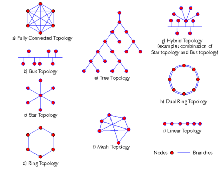
Figure 6. Network topology. Source: wikiwand.com
Among the relatively classical architectures, we find in particular :
- the star topology: a set of sensors is arranged around a base station. This base station (which is also a network node), unlike the other nodes in the network, has a long-range radio link, for example. The messages from each sensor/node are therefore sent to this base station at short range and then sent together, thus avoiding the need to install a more massive communication structure on each sensor. It is possible to imagine that a sensor is also present on this base station. For example, we could have connected soil moisture sensors on each of the nodes of the star and a weather station connected to the base station. In case it wasn’t obvious, keep in mind that the communication goes both ways. The base station can receive information from adjacent nodes in the star but also send information to them (for example to update a code on a sensor). Not surprisingly in this type of topology, these networks can be considered vulnerable because it is the base station and only the base station that sends data out of the sensor network. It is therefore necessary to make sure that it does not get into trouble…
- the grid or point by point topology (also called multi-hop communication): here each node of the network can exchange with any other node of the network if these two nodes are at a distance that allows it (depending on the communication protocol used). If the distance between the nodes is too great, a node will contact its target node by passing through intermediate nodes. This architecture appears to be more resilient and flexible (we do not rely on a single base station and we have information redundancy) but it requires a little more energy consumption and potentially imposes latency, especially if the message must pass through several intermediate nodes before arriving at its destination.
- Group topology: here the sensors of the network are hierarchical. Each sensor can communicate with all the sensors below it in the hierarchy (by passing through intermediate sensors) and can only communicate with one sensor above it (its sensor/head node). And it is this head node that can communicate with other head nodes of the same level (which are on another hierarchy) or directly with the base station. As with star networks, this sensor organization is quite sensitive because the failure of a higher-level object causes the failure of the objects below it. Please do not see any parallel with enterprise organization forms (oupsi).
In these topologies, the communication between sensors or the routing of information within these networks can be considered as proactive or reactive. In the first case, the data are sent back at regular time intervals or at least on a chosen time step (we speak of time-driven communication). In the second case, the sensors must be able to react quickly to important variations of the parameter they measure.
All these topologies and routings can of course be combined, forming so-called “hybrid” topologies. In view of the previous figure, the possibilities of organization seem infinite. The choice of architecture is then often governed by a certain number of constraints and/or the context of use of the sensor network. In particular, we will take into account the size of the network to be deployed, the financial budget available (which also constrains the size of the network but especially the type of sensor chosen), fault tolerance (i.e., the extent to which it is acceptable or not to have interference or connectivity problems), the location of the sensor network (and thus constrains the communication protocols used), or even the energy consumption within the network).
A quick aside. In a star topology for example, the base station is considered as a gateway in the sense that it bridges the gap between the connected sensors and the Internet. Generally speaking, and if we leave the simple agricultural context, examples of gateways are extremely numerous: home routers, cell phones, Raspberry Pi microcomputers, Arduino electronic boards. Gateways ensure connectivity, security and management of connected devices (translation of communication protocols, network aggregation…).
Connected Objects Dynamics
The global market forecasts for connected objects are going to a crescendo… I’m not at all telling you to follow these forecasts to the letter because some of these prophecies are simply self-fulfilling (we go along with the forecasts as if we were destined to achieve them) or simply made with a wet finger. Even if these predictions are a bit preposterous, we have to admit that the topic of connected objects interests a lot of different industries. The second graph also allows us to take a look at the types of connectivity being considered. This growing demand for connected objects is made possible by all the advances in the miniaturization of components (microcontrollers, chips, etc.), the accessibility of tools (sensors, etc.), the development of networks, and the cost of components
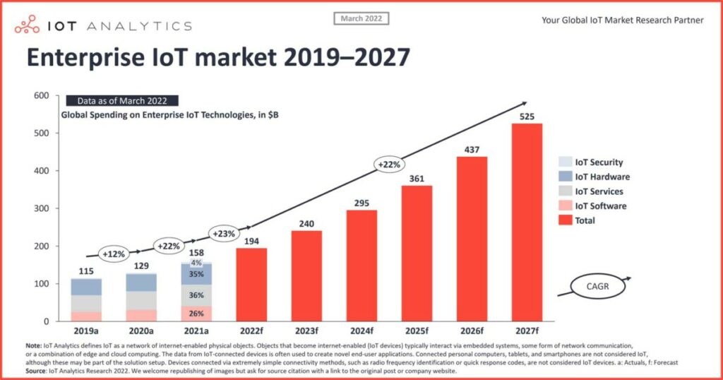
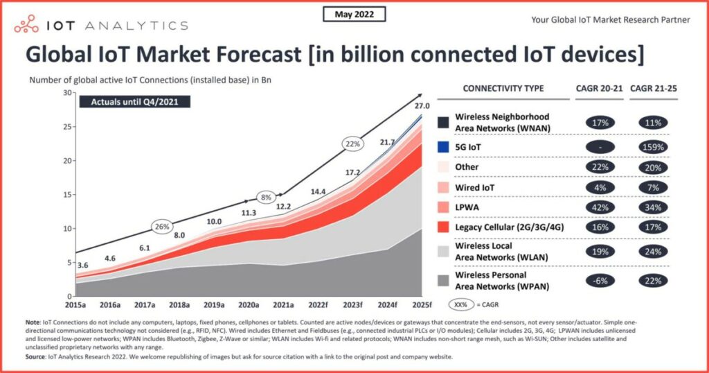
Figure 7: Internet of Things market dynamics. Source: https://iot-analytics.com/
How can we explain the dynamics of connected tools in the agricultural sector? The reasons are actually quite numerous. It may already be a matter of price. Connected objects, especially if they are made by farmers themselves, can be obtained at a relatively low price – depending on how much time one is willing to spend on them. The unitary sensors presented in the next section are for some in the order of a few euros. To connect them, you will have to add at least the purchase of an electronic board, a microcontroller and a telecommunication module (chip or antenna). The whole thing remains affordable if you don’t want to deploy too many connected sensors either. However, when choosing between a few good quality connected sensors or a large batch of low-cost but less good quality sensors, it will be necessary to find a compromise. Considering the potential large surface to cover in agriculture, accepting to deploy a large number of sensors at the expense of data quality is also an interesting way to identify underlying trends. In this sense, it is also an interesting compromise for aggregating data on different territorial scales (for biomonitoring, for irrigation management on a relatively large territory, or more generally to support political decision-making).
With the democratization of smartphones, farmers have also had the opportunity to install professional applications on their phones and thus potentially access in real time data collected from sensors in the field.
Connected objects also seem to be a good way to save time and avoid travel. For those who read my previous report on digital tools in beekeeping, I learned for example that the main economic burden of a beekeeper was related to his travels. The example given earlier in this file about the pumping station to avoid unnecessary trips also seems to be common sense (the fact of having a fragmented parcel of land and/or far from his main farm site is another issue). Collecting data remotely and in real time would also allow to analyze and process the data at the right time
To be fully transparent, it will also be necessary to display the logistical constraints related to such a deployment of connected objects.
These constraints are already present in the maintenance and repair of connected objects (interrupted data transmission, damaged sensor, obstacle or clutter of the sensor…) which can affect the quality of the data sent back (or even prevent data transmission). Even if these requirements are not necessarily the responsibility of the farmer – some service providers may have a very good after-sales service or some collectives may join together to manage a network of sensors, the technical debt linked to poor maintenance or repair cannot be totally avoided. And to be sure that these problems do not recur, it will be necessary to try to link incidents to events in the operation: When did the object stop transmitting? For what potential reasons: a storm, a passage of farm machinery, a passage of wild boars?
The maintenance of connected objects is a multi-factorial subject. In addition to the topics mentioned above, maintenance is also related to the energy autonomy of the connected object. If some devices seem to have been designed for several years of autonomy, it is not necessarily the case for all of them. If the sensor is deployed on a plot relatively close to the farm, the constraint may not be too strong. On the other hand, in a pastoral context, with sensors potentially installed on high mountain territories, the lack of autonomy of the sensor is immediately more worrying. Some connected objects will also need to be updated more or less regularly. It will then be important to ask if these updates can be done remotely (via cellular network connection for example) or if they are possible at least from the farmer’s office. It is also important to remember that these updates are not necessarily free of charge and that it will be necessary to check the terms and conditions of sale when purchasing the sensor or the associated subscription.
To avoid damaging the connected objects, some sensors will have to be winterized in the sense that they will have to be stored potentially at room temperature, that the battery voltage will have to be checked and that it may even be necessary to verify that the connected object is turned off when it is no longer used at the end of the season.
We will come back to the issues of connectivity and data transmission of connected objects. Before talking about technology and communication protocols, there are also a number of good practice rules that need to be put in place: sensors not to be placed in the bottom of a valley or near a forest, or to make sure that you get at least one connection bar from an operator for a connection via the cellular network… And then to choose communication protocols adapted to its use (we will come back to this later), to ask yourself if the sensor will work inside buildings or only outside, to question what happens if there is no more data communication (is the data still stored in situ? )
Perhaps a first test of the connected object at the farm’s headquarters is a prerequisite before deploying it in the field, just to make sure that everything is working properly and not to have any unpleasant surprises in the field…
Examples of sensors in agriculture
The agro-environmental applications of connected sensors are quite endless. From the monitoring of migrations and movements of animal populations, to the monitoring of machinery to consolidate databases of operation/breakdowns and imagine, for example, remote troubleshooting, or even for the piloting and real-time control of an irrigation network, you are spoilt for choice.
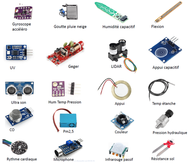
Figure 8. Examples of sensors that can be used in an agro-environmental context.
Are you short of ideas? Here is a small selection of sensors (to be connected or not!). Keep in mind that for each of these sensors (Figure 8), there are different price ranges (and therefore quality).
- “Bending” sensor to be installed, for example, on tractor wheels to dynamically evaluate the pressure of the tires and why not indirectly determine the weight carried by the tractor. Depending on the bending, the metal bars within the sensor come closer or less close to each other to let the current pass (the sensor contains alternating metal and non-metal strips)
- “Temperature” or “rain gauge” sensor: do we really still need to present them?
- “Pressure” sensor, which is based on an operation quite similar to that of the bending sensor (the metal bars are no longer brought closer together by bending but by the ambient pressure). Why not use it to measure tank bottom levels (pressure changes with altitude)
- “Ultrasonic” sensor to measure, for example, grass heights (we talk about herbometer) or more simply distances (the rather unbearable beep of your car’s reversing radar is often based on an ultrasonic sensor). The ultrasonic sensor could also be tested to measure tank levels. Ultrasound depends on the speed of sound (so far so good…) and the speed of sound depends on a lot of things like temperature, alcohol vapors, particle or dirt levels.
- “Microphone” sensor to monitor noise levels and detect presence. This can be used by farmers who are worried about aggressors roaming around their herd.
- “Near infrared” sensor also used to detect presence (and relatively well known in the field of home automation)
- “Capacitive probe” sensor to ensure, for example, that the water from an irrigation network arrives at the end of the line in a drip irrigation system.
- “Multispectral” sensor to be used passively or actively (with diodes on the sensor) to take images of vegetation and to follow the evolution of this vegetation over time (phenology monitoring)
- “GPS antenna” sensor to add a positioning module on an on-board tool on machines. I refer you here to a previous file on geo-positioning in agriculture (https://www.aspexit.com/geopositionnement-en-agriculture/)
- “Chemical” sensor to measure, for example, CO2 or ethanol levels in a room
- ….
And in operational conditions, what does this mean?
Whether they are fixed, hand-held or embedded (on animals, plants, agricultural machinery, drones, airplanes or even satellites), sensors are certainly the most represented category of technology in the digital agricultural ecosystem (Figure 9). Interested readers can find the vast majority of these tools on the Farmers’ Digital Tools Directory, a free, open-access, collaborative platform that lists the digital tools available to agricultural actors.
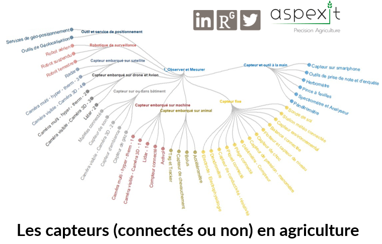
Figure 9: Sensors, connected or not in agriculture. Source : Aspexit
And for the aficionados of agricultural machinery, a small figure to show you the extent of sensors present on some tractors (Figure 10).
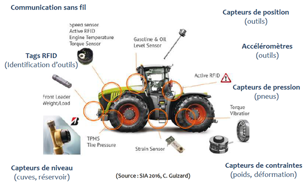
Figure 10: Examples of sensors connected to agricultural machinery.
Communication protocols
What parameters should be considered when choosing a communication protocol?
As we will see, communication protocols are extremely numerous. The idea here is not to go into a list of protocols, which is as boring as possible, and to explain each of these protocols precisely. Some people would have already done it much more finely than me (even if the content is sometimes not really made understandable for the common people). Instead, I will try to bring out the main issues and to give you some elements of comparison that seem relevant to me – by using a lot of figures.
The communication protocol defines the structure, format and size of the messages to be sent. But get this into your head. There is no such thing as “the” ultimate communication protocol that outperforms all others! The best protocol to use depends on your context. To send data from one connected object to another connected object or base station (whether in a wireless sensor network or not), it’s all about the trade-off between :
- The radio frequencies used by the protocol (Figure 11): apart from a few frequencies used in a military context, the defined frequencies are free but they are controlled by ARCEP (French Acronym – Regulatory authority for electronic communications, posts and press distribution) . It is not possible to put the power that we want. For example, Sigfox and Lora networks use the 868 MHz frequency in Europe (it is not the same frequency band in the United States and the fact of using different frequencies between countries can be a problem for the international deployment of a connected sensor provider in agriculture). This 868 MHz frequency is free but controlled by Arcep. The war is raging among telecom operators to buy frequency bands in order to deploy certain communication protocols. Some protocols are also criticized, including 5G, because the radio waves used by 5G could interfere with weather radars
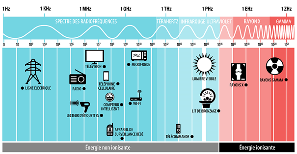
Figure 11. Representation of some communication protocols on the frequency spectrum. These include WiFi, smart meters, cellular telephony and barcode readers.
- The range of the signal sent, that is to say the distance up to which the protocol can carry the information from the connected object to the relay point (smartphone, wifi gateway, relay antenna …). Some protocols used in home automation like Zigbee for example have an extremely low range unlike protocols more widely thought for outdoor sensor networks like LTE-M or NB-IoT. Note that some people have managed to broadcast data via the Lora protocol over very large distances (over 1000 km). Communication protocols are often categorized according to their range, which generally defines their framework of use. One hears in particular to speak – of the shortest network to the longest range – of the PAN (Personal Area Network), LAN (Local Area Network), MAN (Metropolitan Area Network) and WAN (Wide Area Network) networks. For the low-speed networks used in the context of connected objects, you will certainly also see the terminology LPWAN (Low Power Wide Area Network) which are low-speed networks with long range (Figures 12 and 13)
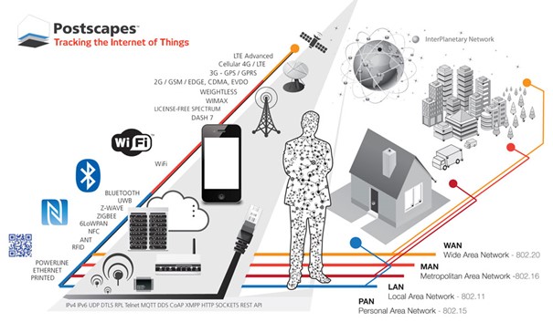
Figure 12. Classification of communication protocols in PAN, LAN, MAN and WAN networks
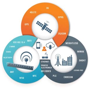
Figure 13. Another representation of communication protocols (with new examples) according to their range. The range is short (blue donut), medium (black donut) and long (orange donut). We could have added also the Infrared technology.
Cellular networks are networks that use radio waves to communicate through the antennas of existing operators. This is for example the case of GSM (2G), GPRS, Edge, 3G, 4G and 5G networks. 3G and 4G networks have “only” a few kilometers of range (2-3 km) but our data is actually transported from antenna to antenna so we can access it from anywhere by paying our subscription. 4G is not optimized for the Internet of Things (IoT). We prefer 4G LTE-M (we should rather speak of 4G-LTE Category M1). Just keep in mind that there are several categories of 4G and that 4G-LTE Category M1 is notably the one that allows to transmit little data on 4G antennas (so it is particularly interesting for networks of connected objects). The use of 4G LTE-M is relatively trivial for telecom operators because they don’t have to install anything extra on their existing relay antennas (there was just a little code program to add on). However, for those who don’t have antennas (like Sigfox or Lora), they had to do it themselves. And this 4G LTE-M allows the equivalent of a LoRaWAN protocol deployed on the existing infrastructure of telecom operators (thus passing through GSM). To be able to use 4G LTE-M, you need to be covered by a 4G antenna.
In addition to 4G LTE-M, you will also often see mentioned the NB-IoT protocol which is starting to take a lot of space and which has hurt Lora and Sigfox technologies, and to a lesser extent the EC-GSM-IoT protocol is deployable on the existing GSM network (2G/3G/4G) with a simple software update.
- The data rate capable of transiting through the protocol over a given time, i.e. the capacity of transmission of upstream data (to the network) and downstream data (to the sensor) that can be sent per second (you may have already tried to measure the quality of your connection at home with simple simulators on the web). In the case of connected objects, the downstream flow is important to consider for maintenance or update operations. We talk about “Over The Air” (OTA) updates in the sense that these updates are transmitted directly to the connected objects without any intervention in person. For networks with too low a throughput like LoRaWAN or Sigfox, this OTA update is relatively complicated or even impossible. Historically, communication protocols were mainly designed to boost throughput and send more and more data. This is not the case for low-speed communication protocols, which have been updated in response to the new needs of connected objects (Figure 14): sending small data, with a very low throughput (less than 1 KB/s) with a very long range (more than 10 km) and a long autonomy (several years). Some people use the term 0G to refer to low-speed networks (such as Sigfox or Lora, for example) because the data rates are lower than those of 1G and 2G. With the Sigfox network for example, you can only send 144 messages per day upstream (from the sensor to the application/interface) of the size of 12 bytes max (a phone picture is 3 million bytes) and only 4 messages per day downstream (sending information to the sensor [update, sleep, activation]). And the size of the messages, I don’t tell you about it. It is neither more nor less than the equivalent of a 12 characters sms.
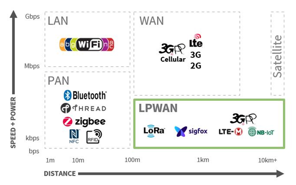
Figure 14. Trade-off between throughput (y-axis) and range (x-axis) of some communication protocols.
- Energy consumption of the connected object and data sending (Figures 15 and 16). Each sensor goes through different phases of data collection, processing, transmission and sending of data. Each of these phases consumes energy (to a greater or lesser degree). The “listening” mode, i.e. when the sensor is ready to receive information from another connected sensor or relay point, consumes energy. It can therefore be interesting to put the sensor in standby mode as much as possible (represented in the figure by the “Stand By” mode). Note that switching the connected object from one state to another also consumes energy. The connected sensors can be either self-sufficient in energy with a battery or a battery pack over a certain period of time or directly connected to an energy source (photovoltaic panel or connection to the electrical grid when possible).
The energy consumption of your protocol is a choice. If you have for example a connected object that already consumes a lot of energy (we can think for example of connected butterfly traps that need to be switched on constantly because we never know when the butterfly is going to enter the trap), the energy consumption due to the data transmission may not be so important to consider.
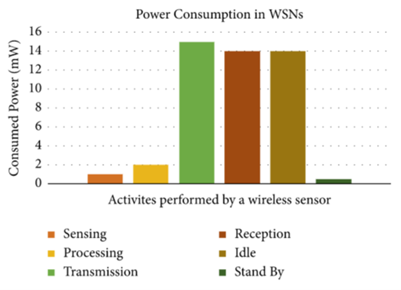
Figure 15. Energy consumption of different state levels of connected sensors. Source: Amengu et al, (2022). SMAC-Based WSN Protocol-Current State of the Art, Challenges, and Future Directions. Journal of Computer Networks and Communications.
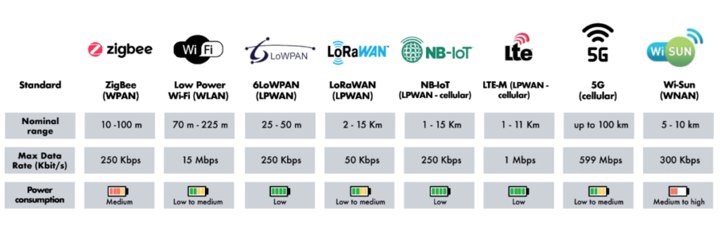
Figure 16. Comparison of energy consumption of different communication protocols. Enocean, not presented here, would be a completely energy autonomous network that could be deployed in completely isolated areas such as in the middle of the ocean.
- Free frequencies or licensed frequencies (understand here that it is paid for in this case). Free frequencies can suffer from unexpected interference or jamming unlike licensed frequencies which are more secure. The price of subscription to the protocol is obviously not the same. It will also be important to ensure the compatibility of connected objects with these frequencies used by the protocol.
- The choice of an operated network or a non-operated network. In the case of an operated network, the telecom operator (e.g. Orange, Bouygues…) manages its own network and takes care of the maintenance of these infrastructures (antennas, relay points…) and potential connectivity problems in exchange for the payment of a subscription fee (basically, the connected objects are deployed and the telecom operators take care of the rest). This is for example what happens with the Objenious network (deployed by Bouygues, it is a LoRaWAN operated in bulk) dedicated to connected objects or the Sigfox network. In the case of non-operated networks, the user creates his own connection to the network without a third party operator. This is for example the case of the LoraWAN protocol where anyone can enable the passage of data between the LoRaWAN network and traditional IP networks by connecting to an existing LoRa antenna or by installing his own LoRa base station. The Things Network (TTN) is a community network that lists all LoRa base stations (gateways) to which a connected object can connect free of charge. TTN sells LoRa boxes with the objective that users deploy a LoRa network near their home. TTN also does data integration with several options available (TTN’s own database which can be queried, MyDevices module to retrieve data from your smartphone…). The coverage of this network depends on the stations already installed. Note that, for this example, the main telecom operators have also deployed their LoRaWAN network through their own infrastructure (you will have to pay in this case a subscription while in the case of a non-operated network, you will only have to pay the cost of your antenna). Note also that a service can combine different networks (e.g. a personal LoRaWAN network to capture data from several sensors and send them to a datalogger and a sigfox network to send data from the datalogger to the server). Other examples of non-operated networks are the Wifi and Bluetooth protocols.
- The overall cost of the network, both that of the “hardware” part, i.e. the type of sensors installed and the number deployed, but also the cost of the subscription to the communication protocols, which will depend on all the characteristics we have discussed above.
- The compatibility of sensors with communication protocols. With The Things Network (TTN) for example, users who are a bit geeky are able to go and do a bit of work on their own by going to the TTN website, defining a communication protocol and purchasing connected sensors that are compatible with The Things Network. You can even buy a pre-configured sensor and it’s your Agtech or other supplier (e.g., a weather station manufacturer) that can potentially make the connection to that sensor. However, if you buy a sensor that is not compatible with TTN, it is immediately more complicated and it can be particularly annoying if you had bought a The Things Network antenna for example. We will discuss a little later the new protocols “Matter” and “Thread” which are intended to become globally unanimous in the sense that they could make connected objects communicate directly with each other rather than going through a global server
And each communication protocol has generally interesting performances on one or more of these criteria and on the contrary much more limited successes on the others… How to choose the most relevant communication protocol for its use case in all this mishmash? The answer is not obvious, but all the characteristics discussed should help you to see more clearly. I would like to take this opportunity to add a decision tree with a few touches of humor, which may also provide you with a few keys to reading (Figure 17).
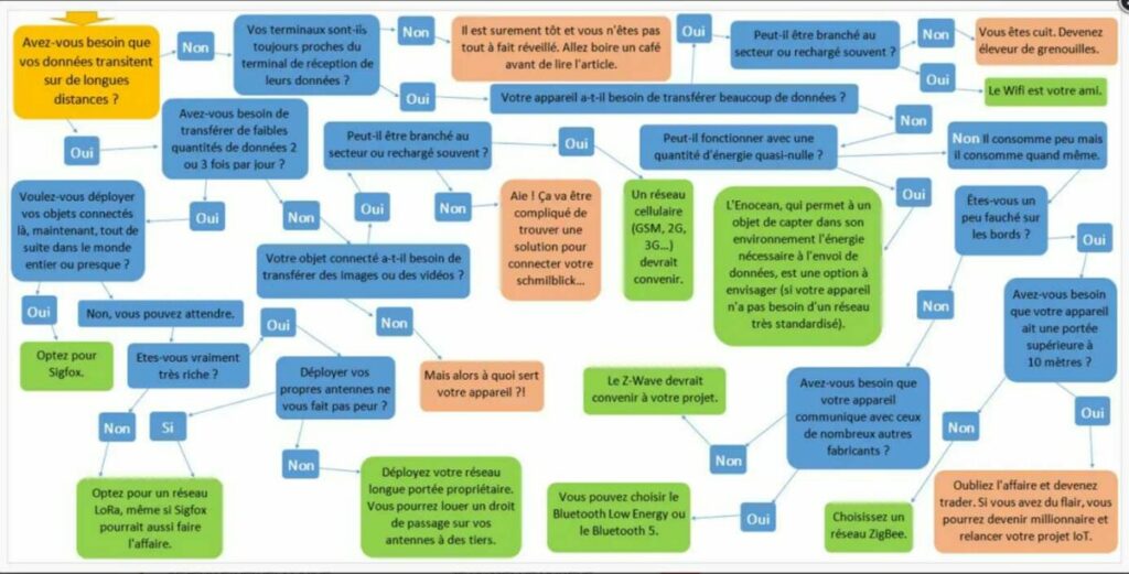
Figure 17. Decision tree to help choose a communication protocol. Source : eMind
I would like to add here an infographic that speaks for itself – and which is also recontextualized for agriculture – which looks at the use of the protocols that we have mentioned (Figure 18). You can see, for example, automated equipment in livestock buildings (e.g. gas and environmental sensors, connected cameras, etc.) that communicate via relatively short-range protocols (RFID, WiFi, Bluetooth, etc.) with their relay point. You will also find sensors connected to the field (connected weather stations) or embedded on machines which will communicate via cellular or non-cellular LPWAN protocols (3G, LoRa, GPRS, Sigfox, NB-IoT…). All this data, stored on servers, will be queried by different APIs served by suppliers and rendered on user interfaces (smartphone, tablet, computer…).
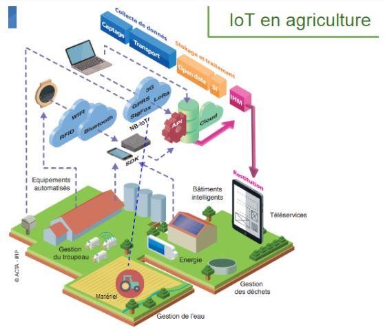
Figure 18. Connected objects and the path of data in agriculture. Source: ACTA and FRCUMA Bretagne
The special case of satellite IoT
A short aside on IoT data transmission via satellite which, even if it represents a very small part of the communication of connected objects, is still a way that deserves at least a small presentation. Considering the range of the communication antennas (a few tens of kilometers), you will certainly agree that deploying antennas over the entire globe is somewhat tedious and especially difficult to set up in some places on our planet – starting perhaps with the oceans (and I skip all the other associated issues…). With the communication of connected objects directly via satellite, the idea is to use satellites as both receivers and transmitters of data. The connected object will synchronize with the satellite to send it its data when the satellite comes into range. The satellite will then unload all this data a little later when it passes over a base station located in a rather accessible place. This station, connected to the internet, will transfer the received data to a server that can be made available to users.
TinyGS is an application that proposes to deploy small connected objects that will receive satellite data. Several other projects exist in this sense, both open source (Fossa-Sat1 which uses LoRaWAN technology via satellite – the transmission range would be potentially very large if the beam of a connected object was pointed towards the sky) and commercial (the company Kinéis – former manufacturer of Argos beacons, and the company Lacuna Space are examples). Currently, a transmission as it is by satellite (and given the number of satellites), offers a relatively high latency time (we are talking about 6 hours, which is incompatible with a fire sensor). Elon Musk’s Starlink initiative, whose objective is to offer an internet connection by satellite, would require an absolutely gigantic number of satellites in orbit for a rather limited flow anyway. We could imagine a wifi connected object (maybe a version of wifi dedicated to IoT) to communicate by internet via Starlink (provided we have a sufficient power source, and the space to deploy an antenna).
Received ideas and abuse of language
First abuse of language so democratized that we don’t even pay attention to it anymore: The Internet and the Web are not the same thing. The Web, globally, is the content and the Internet is the way to transport and access this content. The Internet is the set of computer architectures (cables, antennas, servers…) whereas the Web is the online documents (the pages/websites). Internet is based on the TCP/IP protocol and on an access to Internet (via an Internet access provider). We have seen that there were many communication protocols to connect to the Internet and that the Internet of Things allowed to connect physical objects (for example sensors in the field) to the Internet. The Web is based on a system of hypertext links and requires a browser (Chrome, Firefox, Safari) to access the sites on the Web. To access the web, you need the Internet but you can do other things than just go on the web with the Internet. You can send and receive e-mails on your mailbox, access FTP servers to share data etc…
Second surprise: When you make a phone call, the communication does not go (in great majority) by satellite, no… I take the opportunity to slip here that the GPS works without internet because it is satellite (that’s why when you cut the internet, you still have a position on your smartphone applications). The GSM network (Global System for Mobile Communication – it’s the 2G), which was specially designed to make calls and send SMS, runs in large copper cables that are present all over the world. The GSM network is divided into a sort of “cells” created by base stations (the range around the base station) whose mesh depends on the population to be covered. The connection to the GSM network is done by the SIM card (Subscriber Identity Module) that you have in your phone. This SIM card is an identification key on the GSM network that will encrypt your communication to secure your exchanges. Generally, you use a single-operator SIM card, which means that you use the telecommunications infrastructure of a single operator. It is possible to use multi-operator SIM cards (as proposed for example by the companies Matooma or Things Mobile which have negotiated roaming contracts in many different countries) in order to scan all the networks available in a given space and to connect your sensors to the best network at the moment and thus limit the risks of communication loss. Can you imagine having to manually change your connection and SIM card every time you switch from 3G to 4G, or to WIFI when you arrive home?
The fact that you can easily change network is called “Roaming”. Roaming is rather well managed with the GSM network and is for example not available on Sigfox or LoRa networks. To optimize the connection of your connected objects to the GSM network, you can therefore buy multi-operator GSM IoT packages with billing often based on the amount of data transmitted per month and per sensor. Nothing prevents you from also having several communication protocols directly installed on your connected object. For example, you could imagine two communication boards – one that would use GSM and another that would use Sigfox. This could be interesting if you deploy your connected object in several countries where some of them would not have enough Sigfox antennas installed, which would limit the network coverage of your connected objects located abroad (unlike the GSM network which is better disseminated in the world).
Some connected objects are able to work with SMS protocol but telecom operators tax more SMS than the few kilobytes of data that go through a 2G protocol (it’s the GSM network) or other. Millions of connected objects work in 2G (alarm systems, call buttons, diagnostic systems where we are not going to do maintenance quickly…). Nevertheless, 2G is expected to stop, especially because 2G consumes a lot of energy compared to the amount of data sent. But because of its massive use for IoT, its shutdown is being postponed as the deadline approaches. It may well be that 3G (ultimately more obsolete) will be disconnected before then. We can note that the United States have already started to disconnect the 2G.
When we tell you that a connected object does not communicate, you have to understand that the subjacent technological choice that has been made (in terms of communication protocol for example) does not allow communication. It remains a choice, potentially quite legitimate, but there could have been others.
Cellular networks and Wifi require a phase of attachment to the network and a validation phase, which increases the time needed to send a message, unlike more basic radio networks such as LoRa or Sifgox which do not confirm the receipt of messages and do not dialogue with the network.
The OSI model and networks
This section is perhaps a little more technical than the others, but it has the advantage of being able to take a step back from what we have discussed in the previous sections. The OSI (Open Systems Interconnection) model is a representation of the relationships that exist between all the computer elements of a network and which allows us to see how data transits from a point A to a point B.
The OSI model is presented in 7 distinct layers, 3 of which are hardware layers (known as low layers) and 4 high layers (Figure 19). For example, the data from the connected sensors are transmitted on the physical network (components, cables, sensor pins, etc.) in binary form (0s and 1s). The first 8 bits of a binary series constitute the message frame, i.e. the MAC (private) address of the sensor. We have already discussed this, but the connected objects are not directly connected to the Internet. Don’t forget that the “i” in “IoT” stands for Internet! The Internet of Things allows to connect the objects of the physical world to the Internet network. This connection is generally made through gateways (or antennas) that provide intermediation. The existence of these gateways is due to the fact that the Internet is not dimensioned to manage the addressing of billions of connected objects and that the TCP IP/V6 protocol (layers 3 and 4 of the OSI model) is a protocol too heavy to be exploited directly by the connected objects. The highest layers of the model, especially the very last one – layer 7 – is the one closest to the end user and it is the one we, as users, have to deal with directly. It is for example this layer that creates the interface between the human and widely democratized applications such as the web browser or the mailing service.
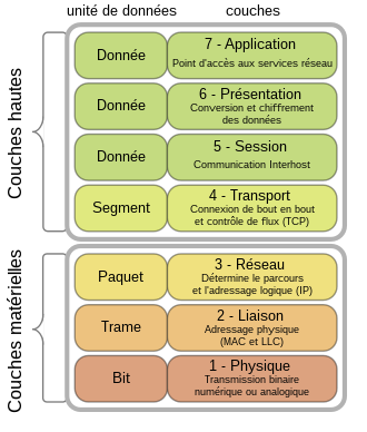
Figure 19. The 7 layers of the OSI model
The OSI model is a theoretical model and the practical (simplified) representation is rather the one we know under the more classical name of the TCP/IP model (Figure 20). Note also that not all equipment uses all the layers of the OSI model. Some, like routers, for example, only need layers 1 to 3.
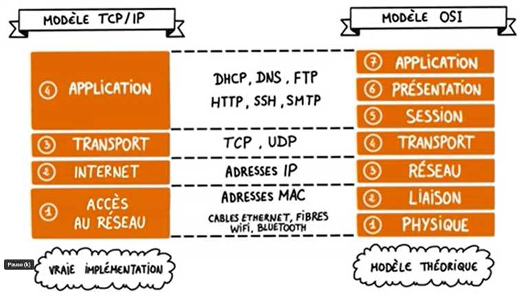
Figure 20: TCP/IP model and OSI model
When two people (let’s call them people 1 and 2) communicate with each other, for example, it is important to understand that the data passes from the “Application” layer (layer 4 of the TCP/IP model or layer 7 of the OSI model) of computer 1 to the “Application” layer of computer 2 (to be accessible from the browser of user 2) by passing through all the layers of the OSI model (Figure 21). The data from computer 1 is encapsulated (we go down in the layers of the model) to be transmitted in binary format (bits) in the network and then desencapsulated (we go up in the layers of the model) to be accessible by user 2.
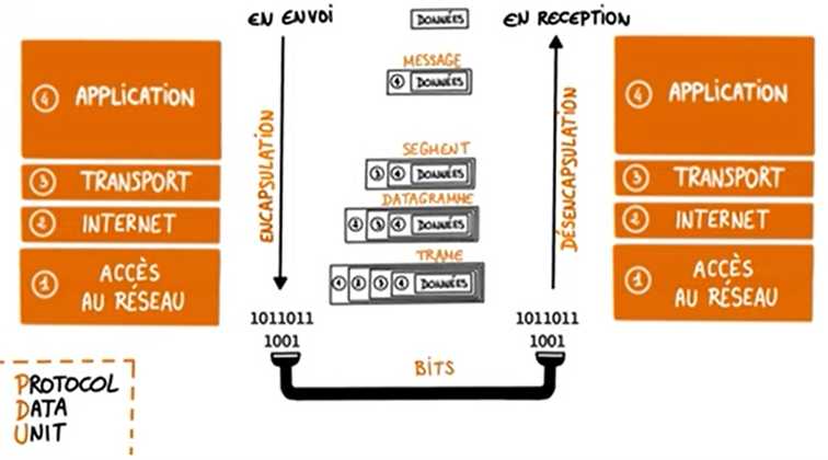
Figure 21. Modeling data transfer between two users with the TCP/IP representation.
Each of the layers of the OSI model involves different protocols, and some of these protocols play a role in several layers at the same time (Figure 22). This specificity means that the protocols of two different layers are not really comparable. Figure X places several of the protocols we have discussed on the same diagram and relates them to their place on the layers of the OSI model.
You can see, for example, that the LoRa and RFID protocols are only protocols for transferring binary data, that the Bluetooth protocol intervenes on both the “Physical” and “Link” layers (the use of Bluetooth for connected objects would only have occurred with the appearance of Bluetooth Low Energy – BLE – in order to limit data rates and thus energy consumption), or that Zigbee is only used for transporting data on the Internet network The interest of Zigbee is to create a simpler and cheaper WPAN network than with traditional technologies such as Bluetooth or Wi-Fi because the user has control over the protocols used on layers 1 and 2 of the OSI model.
To come back quickly to LoRa, make the distinction between the Lora protocol, which defines the functioning of the layer 1 (Physical) and the LoRaWan protocol, promoted by the LoRa Alliance which touches the layer 2 (Link). You may have understood that it is not because your sensor is LoRa compatible that it is necessarily LoRaWAN compatible. LoRaWAN uses the Lora technology to communicate but there is a Lorawan protocol which is one way among others to encapsulate the LoRa technology. LoRaWAN is a standard that is made so that the different LoRaWAN compatible connected objects communicate with LoRaWAN antennas without having to bother with frequency management issues (spreading factor, chirps…). So you don’t have to use the LoRaWAN protocol to work with a LoRa chip. On the hardware level, you could even use a LoRA chip and not have it transmit data with the LoRa protocol (the chip can transmit with any frequency modulation…).
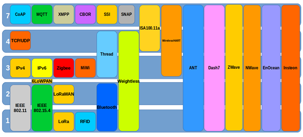
Figure 22. Representation of different communication protocols on the layers of the OSI model. Source: Linux Embedded.
And for the most geeks among you, I found a figure that goes into great detail on the different protocols that you can find at each layer of the OSI model (Figure 23)
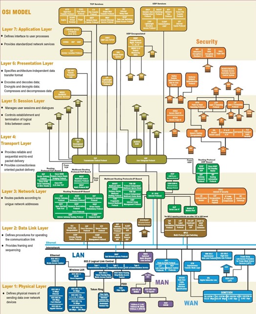
Figure 23. The OSI model and communication protocols in detail.
The MQTT messaging server
It is difficult to talk about connected objects without mentioning the MQTT (Message Queuing Telemetry Transport) protocol. MQTT is a protocol that is particularly well suited to transporting data from connected objects over the Internet (Figure 24). If we take the OSI model from the previous section, MQTT is located at layer 5 (the “session” layer) just above the TCP/IP network layer. The MQTT protocol is therefore routable through the Internet. When sending messages from objects connected by Wifi or Ethernet, it is rather interesting to send them in MQTT because the message is light and there is enough security so that the message is not lost in nature (we will come back to this later). In terms of comparisons with other protocols we’ve discussed, The Things Network is positioned more at application layer 7 of the OSI model while LoRa technology is more at layer 1.
MQTT should be understood as a kind of messaging server for connected objects (a bit like Discord or Instagram) where each connected object would “publish” its data on the server; the server could then rebroadcast this data to a whole host of diverse applications. The users (which can be other connected objects or applications) come to “subscribe” to the publication thread or topic (really like a topic on Discord or Instagram) to see the available data. For example, we can imagine a “temperature data” topic on the server that would store temperature data sent by a temperature sensor. In the context of MQTT, rather than talking about a server, you will hear the term “MQTT broker”. This MQTT broker can be installed on a laptop or on a Raspberry Pi microcomputer. The “Mosquitto” utility, for example, allows you to turn your computer into an MQTT broker. You can also use the Mosca JS device which is a full-fledged MQTT broker.
One of the main interests of MQTT is that it introduces the notion of Quality of Service (QoS), that is to say that this device allows to make sure that the data sent has been received. Contrary to the Sigfox communication which uses a communication via radio without data confirmation (the message is sent 3 times but if the message is not received by any antenna, the connected object has no idea that the message is received by any antenna because there is no downstream communication to the connected object), the QoS device, with its different reliability levels (QoS 0, QoS 1 and QoS 2), ensures a round trip between the connected object and the MQTT broker and thus limits the potential loss of messages. By taking a step back, MQTT can thus be seen as a message encapsulator, a way of communicating to be sure of having received the message to be transported.
Figure 24 shows an example of the use of the MQTT protocol. A temperature sensor connected to an Arduino board transfers its data encapsulated in MQTT via a WiFi module (installed on the Arduino board). A MoscaJS MQTT broker decodes the MQTT message and transfers it to a Raspberry Pi microcomputer. Note that the MQTT broker is on a local IP address of the network and the connected objects must be aware of the IP address of the broker to be able to send messages to it. The Rasberry Pi is in charge of either storing the received data on a local database or sending it to a third party database (which will be for example queryable by API). The data could either be made available always in MQTT (many applications are able to open MQTT) or converted (in .json format for example) upstream. For a connected sensor located in an agricultural plot, one could have imagined sending the data via GSM to an antenna. The antenna could, via a dedicated application, encapsulate the data in the MQTT protocol before sending them to the rest of the network.
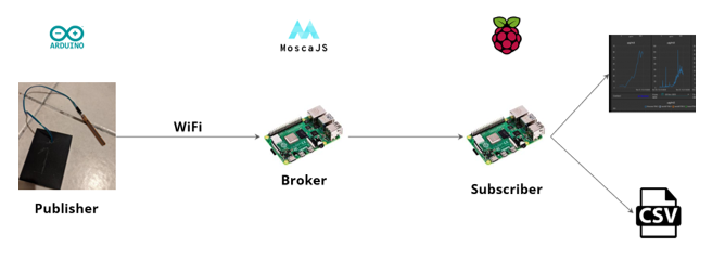
Figure 24. Example of the use of the MQTT protocol. The red fruit is the symbol of the Rasperry Pi. Credits: Simon Moinard.
To be completely honest, I should have told you that the MQTT broker acts as a messaging server, but at some point you have to tell it what to do. Node-Red is a programming tool that is used to manage communication protocols between servers and interfaces and is also comfortable with MQTT requests. The Node-Red application will be used for example to explain that the MQTT brocker gets an MQTT message from a temperature sensor, extracts the temperature data from the message, and then sends this data to wherever we want. You can for example send it to the “ThingSpeak” platform (https://thingspeak.com/) dedicated to IoT, to store and display the data coming from your sensors. This platform is able to receive messages directly in MQTT.
The Matter and Thread protocols
You may also have seen the names of new protocols that are starting to gain ground since the end of 2022 – notably “Matter”, “Thread” and “Amazon Sidewalk” pushed by the giants of the domain (Amazon, Google and consorts). These are more home automation oriented protocols so I can’t really say if we can expect anything from them in agricultural applications. Nevertheless, the announced ranges of some of these protocols (several hundred meters) could be of interest to many.
Matter and Thread seem to be protocols derived from Zigbee but adapted to IP communication. With the Matter and Thread protocols, all the elements of the network (connected sensor for example) know the IP addresses of the other elements of the network, which means that each node of the network can send its data to another node of the network without passing through a central unit. In the case of the MQTT broker we mentioned, you will have understood that it is this brocker that makes the link between all the sensors in the network. If this brocker fails, there will be no more messages instantly because each sensor communicates at the address of the MQTT broker. However, this is not so problematic because I remind you that the MQTT broker has a verification system to make sure that the message has been sent or not (so in quotes, if the brocker has a problem, it knows that it has not sent the message).
If we come back to Matter or Thread, the use of these protocols means that all your connected objects in the network are compatible with these protocols and that we don’t have to worry about the data exchanges between the nodes of the network. For example, it will be enough to add a Matter compatible object (for example a temperature sensor) in our network. If the thermostatic head of my radiator is also Matter compatible, my MQTT broker or my home automation box is not really interesting anymore because the thermostatic head of my radiator can directly communicate with my temperature sensor and use it as a reference to adapt the temperature of my home.
What happens in comparison without this Matter protocol, i.e. if I use for example my MQTT broker? In this case, I would need a home automation box to save the data from the temperature sensor and the thermostatic head of my radiator would query the database at my box using the brocker as an intermediary, and the brocker would then control the thermostatic head. If we had to summarize the thing, we could simply say that the Thread and Matter protocols allow connected objects to communicate directly with each other rather than going through a global server. This is also the case of WiFi, for example, which allows wireless connection between a computer device and the Internet, but also between several computer objects (for example, between a computer and a printer). Let’s go back to our sheep. The objective, for the suppliers of these protocols Matter and Thread, is that these protocols are already installed by default on the connected sensors.
Let’s try to take a step back
Governance and Open Source in the IoT world
Prototyping your own connected objects is undoubtedly less expensive and allows you to free yourself from service providers and potential technical locks. It is indeed an opportunity to choose your communication protocols or to repair your sensors. But are the communication protocols really accessible to everyone? The subscriptions offered for some IoT protocols (Sigfox, NB-IoT) are still rather oriented towards the corporate world with subscription packs for a large number of sensors to be connected. Apart from a few large farms, it is difficult to imagine a single farmer opening an account with these providers to access their communication protocol. Our gaze also turns to the new protocols “Matter”, “Thread” and “Amazon Sidewalk” pushed by the giants of the field (some again rather oriented towards a home automation use) which question our willingness to always make use of the already well standardized and encapsulated media by GAFAM. IoT protocols – notably 4G LTEM and NB-IoT – have also largely stolen market share from Sigfox and LoRaWAN (although it’s hard to know if this is really the case for the agriculture sector specifically). However, with Sigfox placed in receivership in early 2022, one might wonder if the future of LoRa, for its part, might not lie on the open-source side. We have discussed in this file for example the structure The Things Network seeking to network all LoRa antennas deployed by individuals in their homes.
The low cost of sensors, the easy access to electronic boards and microcomputers of all kinds, and the existence of an absolutely gigantic community around the deployment of open source IoT projects gives the possibility to anyone, with a little bit of motivation and time (especially time!), to get into the adventure (and some risks as well, especially when you expose yourself to 220V). You will then have the pleasure of having to manage yourself the problems of crashing microcontrollers, communication networks that are too weak or available, authentication errors of objects connected to the network or even battery supply issues. Fablabs are flourishing and mobile devices such as the Mobilab from AgroTIC Services are making it possible to raise awareness and/or train agricultural actors directly in the field.
I won’t go into detail here about our dependence on certain companies and countries for the electronic equipment used in connected objects – a dependence that has been brought to light with the semiconductor crisis in 2021 (TSMC company in Taiwan). Semiconductors are essential components of microcontrollers (there are hundreds of thousands of them inside) which are at the heart of the functioning of the Internet of Things. This topic still leaves one wondering about our ability to react to future crises.
Let’s also quickly mention the ability of connected objects to connect some existing devices that are more or less old. For example, we are thinking of solenoid valves connected as retrofits to existing solenoids with a transmitter for each sensor installed. This retrofit, in addition to saving time by monitoring and controlling the irrigation remotely, allows you to keep the existing equipment and avoid buying a new one (potentially more expensive).
Nevertheless, make the difference between a quick prototyping – a bit of a fiddle – and a more solid industrialization of a connected object. Considering the low cost of prototyping, one could be quickly tempted to criticize the prices of some connected object suppliers (well ok sometimes rightly). This is an argument that was raised several times in a previous article on beekeeping and digital technology. However, one cannot have their cake and eat it too… The sometimes high prices of the trade can be justified by a number of considerations: the cost of the associated research and development, the production of the connected objects (with a potential recourse to subcontractors), the shipping and packaging of the sensors, the after-sales service of the supplier, the original certifications (for example the CE certification in Europe), the patent registrations and the intellectual property. Prototyping allows us to test ourselves, and will sometimes be more than enough for the geeks among us, but industrialization allows us to scale up.
Access to connectivity in an agricultural context
The agricultural sector is not like any other. It is a living sector evolving in an open and non-standardized environment. The parcels of land are potentially extensive and/or fragmented – and the parcels are not necessarily close to the farm’s headquarters.
Data communication from connected objects can be limited by signal attenuation issues. Too much rain can actually create an impassable wall of water. Obstacles such as groves and forests, dense vegetation within the plot (e.g. for sensors under the foliage), buildings or even hills can hinder the routing of information. The distance between connected sensors (or between nodes in a network now that you are familiar with these terms) is of course limiting. Repeaters can be used to better disseminate information or to increase the number of nodes in the network.
Communication can also be affected by signal multipath problems, meaning all kinds of bounces that the signal experiences when it encounters an obstacle. These issues are potentially more obvious in an urban context. We can also note interference problems due to cables and wires of all kinds that can be found on agricultural plots – especially for perennial crops such as vineyards or orchards.
In an agricultural context, some sensor networks will be discontinuously connected to their base station, and this for more or less long periods of time. This discontinuous connection can be ensured by using the agricultural equipment – tractor or drone – when it is moving on the agricultural plots (if it is not you who comes to the connectivity, it is the connectivity that comes to you!) These discontinuous connectivity constraints will sometimes require finding alternative architectures to the wireless sensor networks used more conventionally.
In addition, telecom operators do not cover the entire French territory. The concept of “white zones” actually applies to territories where people live and not to any area of the French territory. A network coverage of 99% actually means a coverage of 99% of the inhabitants living in the territory and not 99% of the surface of the French territory. It is true that there are white zones with respect to an operator (for example, you are in a white zone with respect to Orange or Bouygues) but in the countryside, you cannot speak of a white zone only because the operator to which you subscribe has not covered your zone. A real white zone is when none of the operators is present. If you can make an emergency call, it means that there is at least one of the operators on the market that covers (at least a little) your area.
Despite the fact that many communication protocols have been put in place to promote the development of connected objects – even in agriculture – it seems legitimate to question the inequalities in network access and digital inclusion within the agricultural sector (Figure 25). ARCEP (the French regulatory authority for electronic communications, postal services and press distribution) recently launched a website so that anyone can assess the level of connectivity in their commune. ARCEP also provides theoretical network coverage on its “Mon Réseau Mobile” website. This information is accessible via API. Figure X shows the coverage rates declared by farmers (at the farm headquarters and on their plots) following the Agrinaute surveys from 2013 to 2020 that we have concatenated on a dynamic interface.
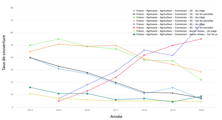
Figure 25. Coverage of farm headquarters and plots in 2G, 3G and 4G cellular network. Source: Aspexit – Aggregation of data from Agrinaute surveys 2013 to 2020: https://aspexit-corentin.shinyapps.io/taux_adoption/
The enthusiasm for 5G raises questions about farms that do not have access to even 2G or 3G at their headquarters or on the surrounding plots. Won’t the deployment of 5G in agriculture further encourage the deployment of connected objects or digital technology in general on certain farms that already have a significant advantage? Similarly, since the Internet of Things is largely accelerated by the smartphone that we almost all have in our pockets, what happens to farmers who do not have a smartphone?
Energy consumption of connected objects
In agriculture, the search for autonomy in connected objects (to avoid repeated trips, especially in hard-to-reach areas) calls for reasoning about their energy consumption, and this is already a good thing. Energy optimization can be done at several levels, both at the hardware level (the components of the connected sensor), but also at the software level to ensure a well thought-out operation of the sensor. We have seen at the beginning of the file that data transmission is particularly energy consuming and that putting the connected object on standby for a good part of the time seems to make sense (when the desired agricultural application allows it). We can therefore think in general terms about optimizing radio communication, managing the sensor’s activity cycles (listening, standby, etc.), reducing the amount of data transmitted, efficiently routing the information between the sensor and its relay point or the rest of the sensor network, and replenishing the battery (type of battery used, solar panel power supply, etc.).
Concerning the reduction of the amount of data transmitted, I take advantage of this section to introduce the concepts of edge computing and cloud computing that we see more and more regularly in the calls for projects. The idea of edge computing, unlike cloud computing, is to be able to process data as close as possible to its acquisition (directly in the field) so as to simplify the data before transmitting it over the Internet. For sensors that collect very high resolution data, such as cameras on tractors, sending the raw image directly to the network is simply inconceivable given the connectivity available on agricultural plots. We could store the data locally on a small computer near the sensor and retrieve it in person using a USB key. But we could also imagine processing the data on this computer in order to greatly reduce its weight. For example, when we take a high resolution image of a weed with a sensor mounted on a tractor, we are really just trying to know if there is a weed or not (and potentially discriminate the type of weed but let’s keep it simple). We will then simply transmit on the network a location data with a presence/absence tag rather than sending the complete image. You will have understood, I hope, that cloud computing consists in processing this data on a server once the data has been transmitted to the network.
Embedding the processing as close as possible to the tool (Edge Computing) then requires embedding intelligence and processing power in-situ, which is not completely obvious either. If the reduction in energy consumption of the connected object is completely offset by the energy required to power on-board processing (and this is particularly the case if the data acquired is heavy and the processing of the data relatively complex), one may wonder if the game is really worth the candle.
If we imagine massively deploying connected objects, even if each one is fairly energy efficient, we always come back to the nagging question of the rebound effect – i.e. the fact that the energy gain obtained (energy efficiency) via the improvement of the energy performance of each connected object considered individually could be swept away by the increase in the number of sensors installed and the quantity of data transmitted. Just take a quick look at the increase in data throughput allowed by 5G compared to 4G which, even with a reduced data transmission efficiency per kilobyte, will again hardly be able to bypass this rebound effect (and I’m not talking here about the necessary construction of antennas to accommodate this new communication protocol). This decoupling between the offered data rate and the amount of transmitted data has never happened before and there is little reason for it to happen again. One can always argue that the amount of data transmitted in agriculture is certainly much lower than the amount of leisure data of the population as a whole (videos of fancy cats in 4K, video feeds on Tiktok and Instagram…). Still, it would be a shame to dismiss this topic in agriculture with a single pretext of order of magnitude.
In an urban context, some clever people will rather lean towards the efficiency gains brought to the whole system. I am of course talking about smart grids and smart cities – a kind of mesh network of connected objects which, thanks to real-time measurements of all our activities, would allow us to save significant energy through optimization and micro-piloting to excess. If the proposal is tempting, the subject of energy sobriety that we should share is often relegated to the background. And it is clear that until now, the promises of these dense networks do not go much further than a few savings in travel for garbage collectors and energy savings in buildings. Philippe Bihouix and his co-authors, in their latest book “La ville stationnaire” (published by Acte Sud), criticize the fact that as cities become denser and more complex, energy and material consumption actually tends to increase, despite the effects of pooling and pooling that we might expect. According to them, there would be an optimal city size beyond which the increase in density would be to the detriment of the ecological impact supposedly avoided.
Security and protection of IoT data
Data is not necessarily encrypted on all the communication protocols we have discussed, which raises questions in terms of security and protection of transmitted data. On classic radio protocols or on a protocol like SigFox for example, encryption does not exist. On the IP protocol, when we arrive on the Internet, the data are encrypted and this encryption is generally stronger, especially with the IPV6 standard in place. Communication protocols using the IP protocol, i.e. those on the “Application” layers of the OSI model that we mentioned, such as Matter or MQTT, benefit from this protection provided by the Internet network. On the other hand, at the local network level and particularly at the router level (we are here on layers 2 and 3 of the OSI model), some security and encryption keys still present some flaws for all the connected objects communicating via WiFi, especially for the relatively old boxes which have not been updated. As WiFi communication is not preponderant for agricultural IoT networks, except perhaps at the farm headquarters level, these issues may not be a priority.
If we are really only interested in a relatively basic IoT or a few sensors connected to the field, we can still wonder what a hacker could do with some plot temperature data… The attacks will nevertheless take place on the servers (of the manufacturer, the operator, a cooperative…) rather than on the sensors themselves, where stored and aggregated data are potentially more interesting.
Interoperability between communication protocols
In a previous blog entry, I discussed the technical and business interoperability issues that complicate data exchanges in agriculture. This issue is obviously still present in the case of communication protocols, even if it is a little less prevalent.
For example, we have mentioned in this report the case of the MQTT broker – particularly dedicated to the Internet of Things – capable of managing the interfacing between different communication protocols. Home automation boxes take care of interoperability at a low level in the sense that they integrate all communication networks in order to aggregate data without going through the manufacturer’s server. All the data can converge to a database operated by the home automation server and a single application hosted on the home automation box can retrieve the data. Still in the case of home automation, I had also quickly mentioned the case of the “Matter” and “Thread” protocols whose objective for their suppliers is to install them by default on the connected objects sold. If these standards are accepted, we could imagine that in a few years, an object that is not Matter compatible will no longer have much value…
This need for interoperability is also masked by the deployment of APIs – sensor manufacturers or telecom operators making data accessible on the server by “simple” request (even if building APIs remains a technical and IT investment for those who implement it).
In conclusion
This blog post has provided a panoramic view of the challenges of wireless data transmission in agriculture using simple or networked connected objects. The choice of sensors and communication protocols is driven by as many parameters as the number of sensors to be installed, the throughput or the amount of data to be transmitted, the available network around the data acquisition site, the energy consumption of the sensors, the cost of the entire sensor network installation (hardware, subscriptions…) or the compatibility of the sensors with the chosen communication protocols. When entering the connected objects ecosystem, one cannot but be immersed in an absolutely fascinating diversity of communication protocols and standards which, at first sight, can leave us completely confused. Nevertheless, if you take the time to dig a little deeper into the subject, or even just to unroll the somewhat abstruse acronyms presented to us, you start to get caught up in the game and you start to believe that you have a little understanding of what is going on.
Connected objects remain a good way to demystify a certain number of computer and digital concepts for farmers. It is already a way to realize that a sensor is not connected by default, and that behind the dematerialization generally put forward is actually a plethora of computer architectures (sensors, routers, antennas, servers …) needed to transmit “simple” data from sensors installed in the field. It is also an opportunity to enter a world where open-source plays a largely preponderant role. Many farmers are waiting for awareness and training sessions to, first, discover the existence of sensors to connect and, second, to prototype connected systems. Since production contexts and objectives vary greatly between two neighboring farms, it is understandable that farmers would like to deploy their customized solutions. However, this prototyping is not accessible to everyone and for the less geeky among us, we will have to accept that the industrialization of connected sensors (if they are really useful) will make connected objects significantly more expensive.
To go further
I invite you to watch some videos of the very good computer popularization channel “Cookie Connecté” on Youtube.
https://www.linuxembedded.fr/2016/03/protocoles-de-communication-frameworks-et-systemes-dexploitation-pour-les-objets-connectes